SATCO s.r.o. comp. - PRODUCTS
A. Basic modular version
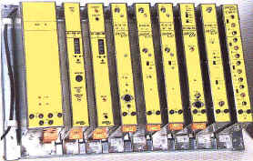
B. 19" racks version
A. Basic modular version
CHANNEL RECEIVING UNIT SC-RSS-201
Channel Receiving Unit SC-RSS-201receives frequency modulated TV signals in
TV cable networks and in systems to transmit TV signals on microwave links.
Receiver SC-RSS-201 is supplied in the following versions:
SC-RSS-201/ST - basic configuration (1 audio stereo channel, a video
filter without an envelope delay corrector)
SC-RSS-201/DS - same as the /ST configuration, but with two audio stereo
channels
SC-RSS-201/ST-LX or DS-LX a super video filter with an envelope
delay corrector
SC-RSS-201/AL - to be used in microwave links
SC-RSS-201/ALS - special configuration for microwave links (audio 7 MHz)
SC-RSS-201/19 - channel receiving unit in 19” rack, mostly in
configuration SC-RSS-201/DS-LX.
The device is in its standard version used to install in the supporting rack or a board in the vertical position, in the configuration /19” it is installed in the standard 19” rack in the horizontal position. Upon request other circuitry - like symmetric audio outputs, output audio and video levels regulation, remote control, other functions on the display - may be added in the version SC-RSS-201/19”.
The receiver unit is controlled by a single-chip microprocessor of the ST series through an I2C bus. It controls all frequency synthesis PLL circuitry, input filter bandwidth switching, video filter switching, video deemphasis switching and regulation of audio parts of Channel Receiving Unit SC-RSS-201. The channel frequency appears on the display after being connected to the Power Supply Unit (NZS-15). The functions are selected with MODE button. Channel Receiving Unit SC-RSS-201 is connected to an external unit through a convenient feeding unit (like Feeding Switch LNB SPI-1750) and Branching Units, if any, like SAP-2, SAP-4 etc.). The coaxial cable terminated by an F-connector (a plug) shall be connected in the F-connector (a socket) in the top side of the cover. The output signals are drawn from the relevant connectors in the front panel.
The channel receiving unit can serve as a video and audio signal source for various external devices or for other SATCO units like TV Modulators SC-M-101 and SC-STM-208, Satellite Radio Demodulator SC-ASR-206, UHF Stereo Modulator SC-SFM-101 and the like. When the Balancing Amplifier SC-ASZ-101/SO is used, then balanced L.F. signals to feed other L.F. equipment can be acquired.
SC-RSS-201 Basic technical data:
received signals features:
| frequency range: | 900 to 2050 MHz | |
| FM modulation video signal in | PAL and SECAM standards(NTSC upon arrangement) | |
| excursion | 10 MHz to 25 MHz with preemphasis | |
| preemphasis | CCIR no. 405 | |
| frequency range of audio subcarrier | 5.5 MHz to 9.0 MHz | |
| audio signals modulation | FM/FM | |
| max. excursion of audio subcarrier | 50 kHz / 85 kHz / 140 kHz | |
| L.F. preemphasis | 50 m s / 75 m s / J17 / Wegen. Panda 1 |
H.F. parameters:
| Tuning range | 900 MHz to 2050 MHz | |
| Input voltage level | -56 dBm to -20 dBm | |
| Input impedance | 75 W | |
| Return loss | > -8 dB |
Video parameters:
| Output video level | 1 Vp-p ± 0.5 dB | |
| Weighted signal to noise ratio | > 58 dB | |
| Differential gain | < 4% | |
| Differential phase | < 3° | |
| Amplitude response to | 5 MHz +0/-1 dB | |
| Disp. frequency suppression | > 30 dB | |
| Output impedance | 75 W | |
| Output level BB (preemphasis OFF) | 250mVp-p | |
| Video output level aut. regulation within excursion | 10 to 25 MHz |
Audio parameters:
| Output impedance | 150 W | |
| Audio subcarrier range | 5.5 to 9 MHz | |
| Output voltage | 0.775 V (0 dBr) ± 1 dB |
General data (modular version):
| Weight | 1.2 kg | ||
| Dimensions | 42 x 146 x 292 (367) mm | ||
| Power voltage | ± 15 V (+4V/-0.3V) | ||
| Max. permitted ripple level of power voltage | (30 Hz to 30 MHz) 100mVp-p | ||
| Current consumption | +15 V max. 550 mA -15V max. 110 mA | ||
| Power connector | WAGO 231-xxx and like | ||
| Output connectors | VIDEO OUT/BB OUT CINCH | ||
| Output connectors | AUDIO OUT DIN | ||
| Output connectors | AUDIO AUX DIN |
Stereo TV Modulator sc-stm-208 serves as a source of the complete TV signal VSB AM particularly to be used in systems of TV cable networks and community antennas. It is supplied in two versions - either in the modular version installed vertically in the supporting rack (e.g. rack SATCO MR-4) or in standardised racks 19”. It is fed from an external ± 15V voltage source (like NZS-15 type, supplied by SATCO s.r.o. company).
SC-STM-208 - basic modular version
SC-STM-208/19”- basic version in 19” rack
Versions according to output frequency:
VHF output frequency in 47 MHz to 446 MHz band
UHF output frequency in 470 MHz to 862 MHz band
KU output frequency in 5 MHz to 30 MHz band (reverse channel)
MF output frequency in I.F. band, video carrier 38.9 MHz or 38.9 MHz (I.F.
output without conversion in TV channel)
MF2 I.F. output with separated outputs for video carrier and audio
carrier without conversion in TV channel - (only in 19” version)
When ordering versions VHF, UHF and KU, the requested standard CCIR either B/G (audio 5.5 MHz) or D/K (audio 6.5 MHz) and required output frequency are to be specified.
Accessories upon request (all versions):
VIF.: equipped with a video filter and a group delay corrector
Accessories only for the 19” version:
XLR: equipped with symmetric audio input XLR 600 W
(stereo)
DO: equipped with remote control by a PC
EXT: External synchronizing frequency input
REG: equipped with regulation of input audio levels or subcarrier levels
(for MF and MF2).
The input video signal is amplified in a video amplifier and after eventual
correction in a video filter with a group delay corrector is brought in an AM
modulator operating on frequency of 38.9 MHz. This signal is amplified and
adapted in a filter block. A signal to decode a VPS signal is diverted from the
video signal. The audio signal goes through preemphasis and audio filters
circuitry in matrix circuitry, electronic switches circuitry and circuitry of an
identification signal generator. These signals modulate I.F. modulators
operating in 32.4-33.4 MHz band. After merging with the video carrier, the
signal goes in a mixer, and the signal of the relevant TV channel appears in
output of the mixer. After filtering parasitic products and appropriate
amplifying, the signal goes in an RF OUT output connector.
Command, control and connected elements are situated on the front panel. Frequencies of the video carrier oscillator 38.9 MHz, of both audio modulators and of the main oscillator are stabilised by PLL circuitry. Reference frequency for the PLL circuitry is brought from a crystal driven oscillator. In the 19” version, the reference frequency can be brought from an external source 4.0 MHz, 6.4 MHz or 8.0 MHz. In such a case the precise offset of output frequency in multiples of 1/6 of horizontal video frequency can be adjusted.
Front panel diodes signalise the operating mode. L16F signalises that the VPS signal is present, ST and DUO indicate the operating mode. The operation parameters appear on the display and some of them can be adjusted with buttons. The Mode button enables to switch between the operation mode (according to the transmitted VPS data line) and the manual mode (manual selection stereo, mono and duo modes), to display video carrier frequency, to change separation between audio carriers and a video carrier, they indicate the VPS and PLL statuses. The modulator activity is controlled by a microprocessor. Output H.F. signal goes in an F-connector and its level is regulated by a RF LEVEL regulating element.
SC-STM-208 Basic technical data:
| I.F. video carrier frequency | 33.9 MHz | |
| 1. audio carrier to video carrier ratio | - 13 dB | |
| 2. audio carrier to video carrier ratio | - 20 dB | |
| L.F. modulation nominal excursion | 30 kHz | |
| L.F. preemphais | 50 m s |
| video carrier output level | 108 dBm V | |
| protected frequency zone | 30 to 862 MHz | |
| ripple factor of output frequency response | < 1 dB | |
| video carrier output level stability | < 1 dB | |
| min. signal to noise separation | 58 dB | |
| output impedance | 75 W |
| nominal input level | 0 dBr | |
| input impedance | > 30 kW | |
| frequency range | 50 Hz to 15 kHz | |
| L.F. preemphais | 50 m s |
| nominal intermodulation level | 85% | |
| intermodulation level stability | ± 5% | |
| differential gain | 3% | |
| differential phase | 3° | |
| difference in gain colour / brightness | 1 dB | |
| video amplitude-frequency responsein band to | 4.43 MHz +1 dB / -1.5 dBto 4.8 MHz - 3 dB | |
| L.F. signal amplitude-frequency response | +1.0 dB / -3.0 dB |
| weight | 1.2 kg | |
| dimensions | 42 x 146 x 292 (367) mm | |
| supply voltage | ± 15 V (+1V/-0.3V) | |
| power connector | WAGO 231-xxx and like | |
| input connectors | CINCH | |
| output connector | F socket |
SATELLITE RADIO DEMODULATOR SC-ASR-206
Satellite Radio Demodulator SC-ASR-206 serves particularly to receive, demodulate and process in other ways L.F. signals modulated on audio subcarrier frequencies transmitted either from fixed space satellites or via microwave links.
The SC-ASR-206 demodulator is supplied in the following versions:
- SC-ASR-206/ST basic version in modular configuration
- SC-ASR-206/AL version for application in microwave links
- SC-ASR-206/19 version in 19” rack, possibly with another SATCO unit
The device in its standard modular version is to be installed in the supporting rack or a board in the vertical position, in the configuration SC-ASR-206/19 it is installed in special holders for 19” rack in the horizontal position. Other circuitry can be provided upon request - like symmetric audio outputs, a change of the audio subcarrier frequency range, additional functions on the display. The operation of the SC-ASR-206 demodulator is controlled by a processor. The front panel functions can be switched using the MODE button. These are the received signal frequency for the left channel, the received signal frequency for the right channel, expander ON and OFF, switching bandwidths of the I.F. filter and of audio preemphasis. The input signal containing audio subcarriers (ie a baseband type signal) is brought in the input BB IN connector. This connector is connected with the BB OUT output connector through a switch. These two connectors can be connected either directly or through a low pass filter. Such connection enables to put several SC-ASR-206 units in a cascade channel.
Audio subcarriers go from the BB IN connector through a high input impedance amplifier in a band pass filter with pass band approx. 5.5 MHz to 9.0 MHz (or a low pass filter to 5.0 MHz). The signal is divided in two independent branches behind it, labelled as LEVý Kanál (left channel) and pravý kanál (right channel), that serve to process two independent or stereo channels.
The output signal goes through a regulation amplifier into a low pass filter with limit frequency approx. 18 kHz which should suppress ultra-acoustic components of an L.F. signal. The L.F. signal branches in two paths then. In the first, a compressed signal goes through expander and deemphasis circuitry in the first input of a change-over switch. The other path processes an uncompressed signal. It passes switchable deemephasis 0 m s, 50 m s (16), 75 m s (17), J17 (18) circuitry and goes into a regulation amplifier and the second input of the change-over switch. The switch selects the signal to be processed either through an expander or linearly. The signal goes from the switch through an input L.F. amplifier in Audio out output cinch connectors on the front panel and audio aux output DIN connectors on the top side of the cover.
SC-ASR-206 Basic technical data
Parameters for input signal:
| input signal - baseband signal in | 20 Hz to 8.8 MHz band | |
| input level of BB signal | 250 mVp-p 6 dB | |
| audio subcarrier input level | 230 mV | |
| input impedance | 75 W | |
| audio subcarrier frequency range | 5.5 - 8.8 MHz (or 1.0 - 5.5 MHz) | |
| frequency increment tuning | 10 kHz | |
| output impedance | 50 W | |
| min. load impedance | 600 W |
Basic transmission parameters:
| audio signal modulation | FM | |
| audio subcarrier frequency excursion | 50 kHz | |
| L.F. preemphasis | 50 m s, 75 m s, J17 | |
| expander | PANDA 1 | |
| L.F. audio signal parameters for linear mode | (EoFF): | |
| output level | 0.775 Veff ± 0.5 dB | |
| signal to noise ratio | > 66 dB | |
| signal to noise ratio linear eff. up to | 20 kHz > 70 dB |
General properties (modular version):
| weight | 1.2 kg | |
| dimensions | 42 x 146 x 292 (365) mm | |
| supply voltage | ± 15 V (+1V/-0.3V) | |
| max. permitted ripple level of supply voltage | (30 Hz to 30 MHz) 100mVp-p | |
| power current max. | 330 mA (+15 V ) max. 30 mA (-15V) | |
| power connector | WAGO 231-xxx and like | |
| input connector | BB IN/BB OUT CINCH | |
| output connectors | AUDIO OUT CINCH | |
| output connectors | AUDIO AUX DIN |
Frequency Converter SC-IC-101 serves to receive TV signal of a ground transmitter and to convert it in I.F. band 32.15 MHz to 40.15 MHz. It is supplied either in the basic modular configuration or in the 19” rack separately or together with Input Unit SC-OC-101. The input unit is supplied factory adjusted for a fixed frequency. The following three versions of SC-IC-101 are supplied according to the frequency range of the input signal:
- SC-IC-101/UHF 470 to 862 MHz
- SC-IC-101/VHF 47 to 470 MHz
- SC-IC-101/KU 5 to 30 MHz (reverse channel).
The input signal is fed to an adjustable attenuation element with PIN diodes. A band pass filter tuned to the input signal frequency follows. The amplifier amplifies the received signal to the level required and balances loss in band pass filters. Another band pass filter increases the input circuit selectivity and therefore provides the adequate rejection of parasitic signals and external noise immunity. An amplifier and a balanced mixer follow behind the second band pass filter. A local oscillator signal is brought in the other input of the mixer and its frequency is fixed and stabilised by a frequency synthesis PLL circuit.
The input signal is converted to the intermediate frequency in the 32.15 - 40.15 MHz band in the mixer. Behind the mixer, a frequency filter follows that suppress higher harmonic frequencies, the oscillator frequency and other undesirable products, if any. The intermediate frequency signal is amplified in an integrated adjustable gain amplifier and fed in the output connector. This filter is of the low pass type usually. At worsened receiving conditions, particularly at processing adjacent and next-to-adjacent channels, the input unit can be complemented with a SAW filter upon request.
Input Unit SC-IC-101 is supplied also in the version SC-IC-101/AV with an input TV signal demodulator. It contains an independent synchronous video modulator and an independent audio subcarrier demodulator. The demodulated output video signal and the audio signal are brought in the CINCH connectors on the front panel.
The device is powered from an external source +15 V (like NZS-15 type, supplied by SATCO s.r.o. company).
Basic technical data of SC-IC-101
Data of the input unit SC-IC-101 itself:
ripple magnitude of amplitude frequency characteristic curve
< 1 dB
input return loss
> 12 dB
output return loss
> 12 dB
return loss output behind mixer
> 16 dB
noise ratio
< 10 dB
signal to mixing parasitic products ratio
> 65 dB
oscillator level to harmonic ratio
> 65 dB
I.F. oscillators level ratio
> 65 dB
- for channels R1 and R2
> 50 dB
IM products ratio
> 65 dB
- in image channel
> 60 dB
oscillators frequency stability
5 kHz
nominal impedance
75 W
automatic regulation range approx.
30 dB
I.F. signal nominal output level
-10 dBm
max. amplification approx.
33 dB
min. input level
65 dBm V
power current
220 mA
supply voltage
+15 V +1 V /-0.3V
weight
1.1 kg
dimensions
42 x 146 x 292 (367) mm
FREQUENCY
CONVERTER - OUTPUT UNIT SC-OC-101
The output unit of Frequency Converter SC-OC-101 converts the I.F. signal in the 32.15 MHz to 40.15 MHz band in the required output TV channel in the 47 MHz to 862 MHz band (for the KU band 5 MHz to 30 MHz). It is supplied either in the basic module version or upon request in the standardised 19” rack together with the input unit SC-IC-101 or as a separate unit.
SC-OC-101 is supplied factory adjusted at a fixed channel. The following SC-OC-101 types can be distinguished according to the frequency range of the output channel
- SC-OC-101/RP 47 MHz to 446 MHz
- SC-OC-101/UHF 470 MHz to 862 MHz
- SC-OC-101/KU 5 MHz to 30 MHz (return channel)
The output unit of the frequency converter is powered from an external source +15 V (like NZS-15 type, supplied by SATCO s.r.o. company).
The input I.F. signal from SC-IC-101 goes to an adjustable damping element with PIN diodes. A low pass filter and band rejection filters, a compensating repeater and a band pass SAW filter follow. Another balanced amplifier amplifies the I.F. signal to the level convenient for the mixer and also enables to adjust the basic gain of the complete I.F. circuit and feeds the automatic gain regulation circuitry AGC. These circuitry consists of a peak detector, a deviation amplifier with an adjusted regulation level and an adjustable damping element with PIN diodes. The regulation voltage is brought through a front panel switch (position “AGC”). The automatic regulation is off in the “MAN” position and gain is adjustable only using trimmer MAN accessible through a front panel circuit.
The I.F. signal is brought through another band filter in a balanced mixer. The local oscillator signal is brought in its second input and its frequency is given and stabilised by a PLL frequency synthesis circuit. The signal is converted on the frequency of the desired TV channel in a mixer. Behind the mixer, there is trap circuitry for the frequency of the oscillator and of the second basic mixing product. The next regulation amplifier enables to adjust the output signal amplitude. The regulating element has a connection to the front panel where it is labelled as “RF OUT”. The signal goes through a main band pass filter, an amplifier and another band elimination filter to a terminal output amplifier. Then the signal goes through an output filter and a matching element to a output connector labelled OUTPUT. The output is of the “wideband” type with output impedance 75 W .
SC-OC-101 Basic technical data
Data of the output unit SC-OC-101 itself:
ripple magnitude of amplitude frequency characteristic curve
< 1 dB
input return loss
> 12 dB
output return loss
> 12 dB
return loss output behind adder
> 16 dB
noise ratio
< 10 dB
signal to mixing parasitic products ratio
> 65 dB
oscillator level to harmonic ratio
> 65 dB
I.F. oscillators level ratio
> 65 dB
- for channels R1 and R2
> 50 dB
IM products ratio
> 65 dB
- in image channel
> 60 dB
oscillators frequency stability
5 kHz
nominal impedance
75 W
automatic gain regulation
ON/OFF
I.F. signal nominal output level
-10 dBm
automatic regulation range
approx. 30dB
output level
108 dBm V
supply voltage
+15 V +1 V /-0.3V (WAGO connector)
power current
290 mA
weight
1.1 kg
dimensions
42 x 146 x 292 (367) mm
STEREO
CODER WITH FM MODULTOR SC-SFM-101
The purpose of Stereo Modulator SC-SFM-101 is to transmit stereo signals in the UHF 87.5 - 108 MHz band that are used in cable TV networks and community antenna systems. It is supplied either in the basic modular version or upon request in standardised racks 19”, together with Satellite Radio Demodulator SC-ASR-206. The stereo modulator consists of a basic printed circuit board fixed in the basic supporting rack. There are an output level regulator and input and output connectors on the front panel. The satellite radio demodulator is powered with ± 15V voltage from an external source (like NZS-15 type, supplied by SATCO s.r.o. company).
The stereo UHF modulator consists of one unit that contains a stereo coder and an FM modulator. The audio signal goes into an input impedance switch and an ON/OFF damping element (-6 dB), into an adjustable gain amplifier. Then switchable preemphasis 50 m s or 75 m s and a Cauer-Chebyshev low pass filter with cut off frequency 15 kHz follow.
A stereo coder with circuitry to compensate cross talk and harmonic components of multiplex signal follows. Then a summation amplifier, a low pass filter for multiplex signal and an output amplifier. Control signals for the stereo coder are generated digitally by a crystal controlled oscillator. The pilot signal can be switched off. The pilot signal level and phase are adjustable. The multiplex signal goes through an excursion regulator into a FM modulator operating at 10.7 MHz.
An isolating amplifier follows that branches the signal in two, then an adjustable attenuator, an amplifier, a ceramic filter with bandwidth 280 kHz, an isolating amplifier and a fixed attenuator -4 dB. The I.F. signal passes in a mixer then.
There is an isolating amplifier in the other branch from which the signal goes in the frequency synthesis outlet. Control voltage goes in a FM modulator that is being tuned to the nominal frequency. Behind the mixer, there are an amplifier with controlled gain, a band pass filter and a parasitic signal trap, then a terminal repeater follows.
The main oscillator signal is brought through a predivider in the PLL frequency synthesis circuit. An input impedance switch for 600 W and preemphasis 75 m s shall be built in according to customer´s requirements.
SC-SFM-101 Basic technical data
a) output signal basic parameters:
| output signal frequency range | 87.5 - 108 MHz | |
| PLL frequency increment | 100 kHz | |
| output level | 108 dBm V | |
| output impedance | 75 W | |
| frequency deviation | 50 kHz | |
| preemphasis | 0 m s, 50 m s, 75 m s | |
| I.F. band width | 130 kHz, 280 kHz |
b) input signal parameters
| input signal | audio signal, Land R channels | |
| input level | 0.775 V or 1.55 V | |
| input impedance | 30 kW or 600 W |
c) Audio signal transmit. parameters
| output level | 0.775 V | |
| frequency response | 30 Hz - 15 kHz ± 1 dB | |
| nonlinear distortion | 0.5% (excursion 50 kHz) | |
| signal to noise ratio | > 70 dB (unbalanced) |
d) Access points:
| baseband input | CINCH socket | |
| baseband output | CINCH socket | |
| audio signal output | DIN socket, 5 pin | |
| power voltage | WAGO connector |
e) General data
| power voltage | ± 15V ± 0.3V | |
| power current | +15V typ. 300mA -15V typ. 50 mA | |
| weight | 1.2 kg | |
| dimensions (modular version) | 42 x 146 x 292 (367) mm |
UHF Radio Converter SC-FMC-101 serves to convert a frequency modulated radio signal transmitted by a ground broadcaster in 87.5 to 106 MHz band (66 to 73 MHz) into 87.5 to 108 MHz band. It is supplied either in the basic modular version or upon request in the 19” standardised rack. The UHF converter consists of a motherboard with printed circuitry, of a module with oscillators and of a separated printed output circuit.
The input signal is converted on intermediate frequency 10.7 MHz. It is filtered and converted back in the UHF band. The input is of the input-output type with impedance 75 W . The received signal goes through three band pass filters in the first balanced mixer and it is mixed with the signal from the first oscillator into I.F. frequency. Frequency of the first oscillator is stabilised by a PLL frequency synthesis circuit. Behind the first mixer, there is an I.F. amplifier with frequency filters with switching bandwidth (280 or 150 kHz).
The signal goes through a limiting amplifier and then it is divided. The first part of the signal is demodulated and goes either as monitoring one directly in the MPX output or from a 50 m s deemphasis circuit in an AUDIO OUT output. The other part of the signal is amplified, filtered and brought in the second mixer. Here, the I.F. signal is mixed with the signal of the second oscillator that is driven and stabilised by a frequency synthesis circuit. The output signal is converted in 87.5 to 108 MHz band. Output signal frequency can be adjusted in this band with 100 kHz increment. Behind the mixer, the signal goes through tunable filters and a trap circuit in output. One of the amplifiers is a controlled-gain one. The output level is adjusted on the front panel using this amplifier.
On the front panel, there are three control buttons and a display that indicates input frequency and bandwidth (280 or 150 kHz). The buttons control output frequency and bandwidth. The typical range of output signal level regulation is 12 dB. On the front panel, there are all input, output and power connectors. The converter is powered from an external +15V voltage source (like NZS-15 type, supplied by SATCO company). The UHF converter activity is controlled by a microprocessor. The tuned-up data are saved in an EPROM memory. Output frequency is adjustable continuously, input frequency is factory adjusted according to customer´s requirements. Input is of the transmission type with branching which allows UHF converters to be used in the configuration without using a branching device.
SC-FMC-101 Basic technical data
| signal modulation | FM | |
| nominal input impedance | 75 W | |
| input level range | 46 to 100 dBm V | |
| input frequency (fixed) | 87.5 to 108 MHz (66 to 73 MHz) | |
| return loss input | min. 13 dB | |
| INPUT/IN-OUT | loss 1 dB | |
| output frequency (adjustable) | 87.5 to 108 MHz | |
| nominal output impedance | 75 W | |
| return loss output | min. 11 dB | |
| output level | 108 dBm V ± 2 dB | |
| output level regulation | min. 12 dB | |
| protected frequency zone | 47 to 860 MHz | |
| parasitic signal at output suppression | min. -60 dB | |
| intermediate frequency band width | 150/280 kHz | |
| distortion | max. 0.2% | |
| frequency response | +0.5 to -1 dB | |
| output frequency stability | typ. 5 kHz max. 30 kHz | |
| power voltage | +15V +1V/ - 0.3V | |
| power current | +15V max. 480mA | |
| weight | 1.1 kg | |
| dimensions (modular version) | 42 x 46 x 292 (367) mm |
UHF BAND AMPLIFIER SC-FMA-101
UHF Band Amplifier SC-FMA-101 serves for band amplification of frequencies in 87.5 to 108 MHz band. It is applicable particularly in systems of TV cable network and community antennas. It is supplied either in the modular version or in the standardised racks 19”, upon request.
The input signal is brought from the input connector in a Cauer band pass filter, then a nominal gain switch follows by which either a damping element (gain 30 dB) or a pre-amplifier (gain 50 dB) is put in the signal path. Then there are a trap circuit for III TV band and a PIN attenuator to change gain in range 0 dB to -40 dB in comparison with the nominal value set by the gain switch. A low level amplifier follows behind the PIN attenuator and part of it is a parasitic signal trap. Behind the amplifier, there are a matching filter, a terminal amplifier with an output level detector and an output filter.
There are two switches and three adjustable several-turn resistors on the front panel of the UHF band amplifier. These regulation elements enable the operator to select a nominal gain, an operation mode (manual or automatic gain control), to adjust the output signal required level and to adjust the wave trap. There are input, output and feeding connectors on the front panel. The device is powered from an external +15V voltage source (like NZS-15 type, supplied by SATCO s.r.o. company). The amplifier has nominal gain 30 dB and 50 dB, which can be selected by a front panel switch. It can operate in two modes:
The amplifier is provided with a NOTCH wave trap that is used in case that one of the signals level is higher than other. The wave trap can be tuned in 65 MHz to 130 MHz band.
SC-FMA-101 Basic technical data
| frequency range | 87.5 MHz to 108 MHz | |
| input and output impedance | 75 W | |
| input return loss | > 15 dB | |
| output return loss | > 10 dB | |
| nominal output level> | ||
| - 1 signal | 108 dBm V | |
| - 2 signals | 105 dBm V | |
| - 4 signals | 102 dBm V | |
| - 8 signals | 99 dBm V | |
| - 16 signals | 96 dBm V | |
| nominal gain | 30 dB (+2.0 dB, -2.0 dB) 50 dB (+1.0 dB, -4.0 dB) | |
| separation S/IP3 | > 60 dB | |
| separation S/N | > 67 dB (B = 300 kHz, gain 50 dB) | |
| wave trap damping | > 15 dB (B = 300 kHz) | |
| wave trap central frequency | 65 MHz to 135 MHz | |
| gain manual change | 0 dB to -40 dB | |
| max. input voltage at automatic level control | 1 V (gain 30 dB) | |
| power voltage | +15V | |
| power current | 240mA | |
| dimensions | 42 x 146 x 292 (367) mm | |
| weight | 1.1 kg |
SIGNAL SWITCH SC-SSW-101
Signal Switch sc-ssw-101 serves to switch H.F. TV and FM signals in cable networks
with frequency up to 700 MHz automatically or manually. It can be used also to switch modulating audio and video signals. Particularly it serves to switch signals from various sources, to backup signals and the like. It is supplied either in the basic modular version or upon request in the standardised 19” racks (only in the 2V configuration).One switch can contain two or four switching sections. More sc-ssw-101 units can be mutually grouped. After the switching sections are mutually grouped, one switch can switch up to five signals in one output.
The switch is supplied in three basic configurations:
- SC-SSW-101/2R contains 4 universal switches
- SC-SSW-101/R contains 2 universal switches
- SC-SSW-101/2V contains 4 switches of audio and video modulation signals
The switching sections operate independently but they can be grouped functionally for some applications. The switching sections of more sc-ssw-101 switches can be grouped, too. Each switching section contains two input and one output connectors. One connector, labelled IN A, is always a priority one. In the 2V configuration, there is identified only the presence of a video signal by analysing synchronising pulses. In the R and 2R configurations, this input is equipped with three modes of signal presence identification that can be selected using a rear-side switch, for each section independently:
- video signal in the baseband,
- H.F. signal modulated by video signal
- unmodulated H.F. signal.
As soon as the selected signal is not present in the IN A connector, the switch switches in the IN B position while continuously following IN A and when the signal appears it switches back in this basic position after some time. The switch is provided also with a CANNON 15 connector where the input and output logic control signals lead. With this connector, manual selection, remote signalling and functional grouping of the switching sections are realised. The manual mode can be used e.g. for purposes of a local information channel.
The switch is powered from an external source +15 V (like NZS-15 type, supplied by SATCO s.r.o. company).
Basic technical data of SC-SSW-101
Identification of signal presence in automatic switching mode
The identification mode for each section is selected using an independent
two-position switch (synchronising pulses - level).
Manual control
CANNON 15 connector, level control, TTL levels, negative logic. Three PINs
belong to each section:
inputs - selection between manual and automatic control,
output - switching section status, effective to chain sections or for remote
indication of switch action,
switching - possibility to switch the section in the manual mode
If the connector is not connected, all sections are in the automatic switching
mode according to the priority signal parameters.
| Switching section frequency range | DC to 850 MHz | |
| Separation damping better than | > 60 dB for f < 700 MHz | |
| Return loss at input | > 14 dB when output is loaded with 75 W impedance | |
| power voltage | + 15 V | |
| power current SC-SSW-101/2R | 430 mA | |
| power current SC-SSW-101/2V | 160 mA | |
| dimensions | 42 x 146 x 292 (367) mm | |
| weight | 1.1 kg |
DUL BRANCHING VIDEO AMPLIFIER SC-VRZ-215
Dual Branching Video Amplifier SC-VRZ-215 serves to branch a video signal from one input in three separate outputs. There are four outputs in the 19” version. There are two independent mutually separated distribution video amplifiers in each SC-VRZ-215.
It is produced in the following versions:
SC-VRZ-215/19” branching video amplifier in the
standard 19” rack
SC-VRZ-215/AV one amplifier (A) with high input impedance
SC-VRZ-215/BNC input and output connectors BNC
SC-VRZ-215/CIN input and output connectors CINCH
SC-VRZ-215 consists of two independent channels labelled 1 and 2. Both
channels are identical. Input impedance is 75 W in
the V configuration and more than 20 kW
in the A configuration. Input impedance is given by a damping element and a
gain regulator in inputs of each channel. The regulation range is approx. +/- 3
dB. The first amplifier with correction of frequency response in the linear mode
follows. An electronic switch behind the amplifier switches the signal in two
paths. The first one is linear. The other is frequency limited. It contains
following circuitry:
video filter of low-pass type with limit frequency approx. 5.0 MHz and first
attenuation pole at 6.5 MHz
group delay corrector which corrects group delay of the video filter
amplifier which corrects filters attenuation and decrease in frequency response
Special equipment:
two frequency wave traps which can be adjusted at approx. 5.0 MHz to 7.0 MHz and which can tune two selected frequencies for approx. 15 dB (e.g. audio subcarrier 5.5 MHz and 5.74 MHz).
The signal goes from the second section of the electronic switch in three (in the 19” version four) independent mutually separated output amplifiers. The amplifiers have unit gain and realise adjusting the output signal DC level. In usual setting, the DC transmission is unit, i.e. without a DC offset. DC offset approx. +/- 2.0 V can be realised upon request.
Input and output connectors are in the standard configuration as
follows:
in the modular version CINCH
in the 19” version BNC
On actual request, the opposite arrangement or combinations of these connectors
can be realised.
Modular version
There are input and output connectors, gain regulation and switches for the video filter (ON/OFF) on the front panel (fig. 2). The power connector is in the lower part of the rack.
19” rack version
Input and output connectors, gain regulation and switches for the video filter are situated in the rear panel. The feeding connector is situated on the rear panel, too. There is the switch and an diode indicating activation of the distribution video amplifier on the front panel.
Basic technical data of SC-SSW-101
a) basic data
| input connector | CINCH (BNC) | |
| input impedance (VIDEO configuration) | 75 W | |
| input impedance (AUDIO configuration) | > 20 kW | |
| nominal input level | 1.0 Vpp | |
| input level max. | 2.0 Vpp | |
| DC shift of input signal average level | max. +/- 2.5V | |
| output connectors | CINCH (BNC) | |
| output impedance | 75 W |
b) typical parameters
| frequency response linear = 0-10 MHz | +/- 0.2 dB | |
| =10-20 MHz | +0.3/-3.0 | |
| frequency response filter 6.5 = 0-5.0 MHz | +0.2/-0.5 dB | |
| = 6.5-20.0 MHz | > 30 dB | |
| Input return loss in 0 - 10 MHz band | > 30 dB | |
| output return loss in 0 - 10 MHz band | > 30 dB | |
| DC shift of input signal average level max. | +/- 2.0V | |
| DC shift of output signal average level max. | +/- 2.0V | |
| gain | 0.0 dB | |
| gain regulation range | +/- 4.0 dB | |
| DC shift between input and output | +/- 10 mV | |
| Channel 1.2 Crosstalk 0 - 100 kHz | > 75 dB | |
| (see Note 1) 0.1 - 2.0 MHz | > 65 dB | |
| 2.0 - 6.0 MHz | > 55 dB |
Note 1
The crosstalk magnitudes are given for the worst case, ie when the signal driven section (e.g. in IN 1) has all inputs (OUT 1A, 1B and 1C) loaded with nominal impedance. The values are better in other cases.
c) General Characteristics
| Power | +/- 15.0 V (+3V/- 3.0 V) | |
| +15 V Power Current | typ. 150 mA | |
| -15 V Power Current | typ. 140 mA | |
| Dimensions | 42x146x292(367) mm | |
| Weight | 1.2 kg |
SYMMETRISATION AUDIO AMPLIFIER SC-ASZ-101
Symmetrisation Amplifier SC-ASZ-101 transforms the symmetric input impedance into the asymmetric output source impedance and the load of the L.F. signal and vice versa in the television cable lines and microwave relay links. It is supplied in two modifications:
SC-ASZ-101/SI Input Symmetrisation Amplifier ( symmetric input -
asymmetric output )
SC-ASZ-101/SO Output Symmetrisation Amplifier (asymmetric input –
symmetric output)
The symmetrisation amplifier contains four independent channels with the gain control feature. Upon request each channel can be equipped with an audio filter. The filter is a low pass unit with bandwidth 15 kHz and the first pole in approx. 15.65 kHz. The front panel contains input and output audio connectors. level regulators, level regulation elements, power connectors and a power indication LED. It is powered from an external source +/- 15 V (e.g. NZS-15 supplied by SATCO).
Input Amplifier SC-ASZ-101/SI transforms a symmetric L.F. signal into a asymmetric one. The input signal is connected via a three-pole audio connector CANNON. It is possible by means of a switch to select a 600 Ohm input impedance. The input signal goes then on through an input amplifier on two jumpers where audio filters can be switched on/off, if built in. The signal then passes through an isolation stage, level controller accessible from the front side panel and an output amplifier. The output asymmetric signal is connected on the CINCH connector (BNC upon request).
Output Amplifier SC-ASZ-101/SO transforms a asymmetric input L.F. signal into a symmetric one. The input signal is connected to the CINCH (or BNC) input connector. Then a level controller accessible from the front side panel and an isolation stage follow. The signal then passes on two jumpers where audio filters can be switched on/off. if built in. An output symmetrisation amplifier follows transforming a asymmetric signal into a symmetric one. The output L.F. signal is connected to the three-pole audio connector CANNON. There is a possibility to switch channel pairs in parallel and to use in the SC-ASZ-101/SO device like a distribution amplifier this way.
SC-ASZ-101 Basic technical data
1. Common SI/SO parameters:
| Regulation Range | +/- 6 dB | |
| Frequency Response without audio filter | +/- 0.2 dB | |
| with audio filter | +/- 0.5 dB | |
| Harmonic Distortion | < 0.1 % | |
| Signal to Noise Ratio linear up to 20 kHz | > 86 dB | |
| Supply voltage | +/- 15.0 V (+3V/- 3.0 V) | |
| Power current | +/- 15.0 V max. 70 mA | |
| Dimensions | 42 x 146 x 292(367) mm | |
| Weight | 1.2 kg |
2. SC-ASZ-101/SI
| Input Impedance | 47 kOhm (600 Ohm) | |
| Nominal Input Level | 1.55 V ef | |
| Max. Overload at Nominal Input Level | +9 dB | |
| Output Impedance | > 50 Ohm | |
| Nominal Output Level | 0.775 Vef |
3. SC-ASZ-101/SO
| Input Impedance | 47 kOhm | |
| Nominal Input Level | 0.775 V ef | |
| Max. Overload ( with respect to the Nominal Input Level) | +9 dB | |
| Output Impedance | 50 Ohm | |
| Nominal Output Level | 1.55 Vef |
TV FREQUENCY MODULATOR SC-TFM-101
TV Frequency Modulator SC-TFM-101 is designed to transfer a TV signal over a microwave channel (a video and its accompanying audio signals are modulated into an inter frequency carrier). The TV frequency modulator is supplied as a part of a Radio Relay Complete for digital and TV signals AL10 transfer in parallel with an especially adjusted channel receiver SC-RSS-201/AL (ALS).
The TV frequency modulator is supplied in the following basic versions:
-SC-TFM-101/AL. the basic version for a microwave relay link
-SC-TFM-101/ALS. the version for a microwave relay link (audio 7MHz)
-SC-TFM-101/A. the version for an audio signal transfer
-SC-TFM-101/19”. the version in the 19” rack (it can be mounted
together with another device)
The TV frequency modulator consists of following functional blocks:
- input video circuits with an input isolation amplifier, a synchronising pulses
separator and AVC circuitry.
- video signal conditioning circuitry consisting of preemphasis and video filter
which can be switched off.
- a video and audio subcarrier signal mixer generating a base-band signal
- base-band signal modulation circuitry generating an I.F. carrier ( typ. 480
MHz etc.) and a carrier stabilization circuitry.
- amplification, filtration, I.F.level control. and output circuitry
- an audio signal input audio preemhasis and input impedance selector
- FM circuitry of an audio signal to subcarrier 6.5MHz (7.0 MHz etc.)
modulation, subcarrier frequency stabilization, modulated product filtration and
its level control.There is also a signal adder where other audio signal
subcarriers from externals modulators are added to the base-band signal.
- a control block providing frequency setting and tuning indication
The TV frequency modulator is microprocessor controlled. The front panel contains power and input video and audio connectors and connectors to connect additional subcarriers and a base-band monitor output. There is also an output connector (type F) and a power and tuning diode indicators The rear panel contains video preemphasis. main audio subcarrier. video filter with a group delay corrector switches and a video modulation polarity switch.
SC-TFM-101 Basic technical data
a) SC-TFM-101 parameters
| Input video asym. | CINCH (BNC) | |
| Input impedance | 75 Ohm | |
| Input level | 0.7 - 1. 4 Vpp | |
| Input audio asym. | CINCH (BNC) | |
| Input Impedance | > 500 Ohm / 600 Ohm | |
| Input level (deviation 50 kHz) | 0.775 Vef | |
| Subcarrier input asym. | CINCH (BNC) | |
| Input impedance | 75 Ohm | |
| Input level (deviation 1.4 MHzp-p) | 91 dBm V | |
| Input frequency range | 6 to 9 MHz | |
| Output base-band asym. | CINCH (BNC) | |
| Output impedance | 75 Ohm | |
| Output video level | 1 Vp-p | |
| HF (IF) modulator output | F connector | |
| Output impedance | 75 Ohm | |
| Return loss min. | 10 dB | |
| Output level | 118 dBm V | |
| Output level control min. | - 20dB | |
| Output frequency ( step 28 MHz) | 424 to 564 MHz | |
| Output frequency stability | 10 -4 | |
| Video deviation ( preemphasis off) | 14 MHzp-p | |
| Audio 6.5 MHz subcarrier deviation | 2.8 MHzp-p |
b) SC-TFM-101 and SC-RSS-201 Complete parameters VIDEO:
| Black level slope | < 2% | |
| P impulse trail slope | < 1% | |
| Static nonlinearity | < 4% | |
| Color-brightness intermodulation | < 2% | |
| Color level deviation | < 5% | |
| Differential gain | < 4% | |
| Output level | 1 V p-p |
AUDIO: (deviation 50 khz. Preem./deem. 50m s):
| Amplitude Characteristic (40 Hz to 15 kHz) | +0.5/-1 db | |
| S/N quasi peak. psofo filter min. | 56 dB | |
| S/N eff. Linear filter to 20 kHz min. | 60 dB | |
| Distortion | < 0.3% |
General Data
| Supply voltage | +/- 18.0 V (+/- 1V +/- 3.0 V) | |
| Dimensions | 42 x 146 x 292(367) mm | |
| Weight | 1.6 kg |
AUDIO MODULATOR SC-AFM-101
Single Channel Audio FM Modulator generates a frequency-modulated signal in the range 0.5 - 9 MHz. It serves as a source of a frequency modulated signal for LF signal transmission. especially over microwave relay links in connection with SC-TFM-101 on auxiliary subcarriers in the range from approx. 7.0 to 9.0 MHz together with a video signal. It is possible to use the audio subcarrier in the range 0.5 - 5.5 MHz to transmit separate LF signals. The input LF signal is connected in an input LF amplifier with low pass filter and preemphasis circuitry. Then an electronic switch follows. which selects either linear or signal compression of type Panda1 operations. The L.F. signal either linear or compressed goes into a FM modulator with IF working frequency 10.7 MHz. The signal then passes through I.F. filters and then an oscillator with PLL controlled frequency and a mixer follow. The mixer produces output frequency within the range 5.5 - 9.0 MHz or 0.5 - 5.5MHZ. Finally there are output filters and amplifiers.
The audio FM modulator is supplied either in the basic module form or upon a special request in the standard 19” rack. SC-AFM-101 composes of a printed card motherboard and a HF module fastened in the module type mounting rack equipped with fastening holes. Controls, indicators and input, output and power connectors are on the front panel. The device is powered from an external +/- 15V DC power source ( e.g. NZS-15 produced by SATCO s.r.o. company)
SC-AFM-101 basic features:
- carrier frequency is PLL stabilized.
- carrier frequency is adjustable with a 20kHz step using front panel buttons. Its value is shown on a display.
- input impedance 30 kOhm or 600 Ohm is switch selectable
- preemphasis is selectable in three steps: 0m s, 50m s or 75 m s
- two operational modes: linear and with LF signal compression. The compressor is similar to the system Wegener Panda1. The reduction of audio signal dynamics in the high frequency range is 1:2, low frequency dynamics is not changed. The compressor mode operation is used for multiple audio signal transmission together with a video signal. The channel spacing is min. 180kHz.
- There is a possibility of cascading modulators to allow transmission of several audio signals.
SC-AFM-101 Basic technical data
b) Output signal parameters c) Input HF signal parameters d) Modulation and transmission parameters signal to noise ratio for nominal deviation e) connection points f) general data
Nominal input level
0dB (0.775 Vef)
overloading - linear mode
+9 dB
- compression mode
+8 dB
input impedance
30 kOhm or 600 Ohm
preemphasis
0m s. 50m s.
or 75 m s
output frequency
0.5 - 9 MHz
frequency step PLL
20 kHz
output level
90 - 102 dBm V
output impedance
75 Ohm
input frequency
0.5 - 9 MHz
input level
102 dBm V
input impedance
75 Ohm
nominal frequency deviation linear mode
50 kHz
compression mode
20 kHz
maximum frequency deviation - linear mode
140 kHz
- compression mode
50 kHz
frequency response
30Hz - 15Hz
- linear mode
+0.5/-1 dB
- compression mode
+1/-1.5 dB
distortion at maximal deviation (1kHz)
0.5%
effectively up to 20kHz linear mode
>72 dB
compression mode
>62 dB
psofo quasi peak to peak linear mode
>62 dB
compression mode
>66 dB
input connector audio
CINCH (BNC) socket
HF connectors
CINCH (BNC) socket
power
WAGO connector
supply voltage
+15V. 300 mA / -15V. -150 mA
weight
1.2 kg
dimensions
42 x 146 x 292(367) mm
POWER
SUPPLY NZS 155
Power Supply NZS-15 provides power for master stations of TV cable networks supplied by SATCO s.r.o. It is supplied either in the basic module arrangement or upon a special order in a standard 19” rack. It is denoted as NZS2-15/19” in the 19” version and it can provide power for up to 2x4 modules SATCO. The power supply NZS1-15/19” can feed up to 4 modules SATCO in the 19” rack. The basic module version feeds one 4-channel set, i.e. eight modules. The power supply NZS-15 is supplied also in a modified version allowing output voltage +/-18V that is used to transmit data on microwaves. It is designed to drive modules by means of WAGO 231-xxx connector. It works on a switching principle and complies with transmission of radio and TV signals in links. On the front panel, there are diodes indicating +/- 15 V voltage on the power connector.
NZS-15 Basic data
| input voltage | 220V/50Hz | |
| input voltage tolerance | +10%/-15% | |
| nominal input current | 0.52A | |
| output voltage | +/- 15V (+/- 18V) | |
| output current | +3.5A/-0.5A | |
| output +15V voltage tolerance | +/- 2% | |
| output +15V voltage tolerance | +/- 5% | |
| +15V output voltage ripple in the 30MHz band | max 150mVpp | |
| -15V output voltage ripple in the 30MHz band | max 250mVpp | |
| protection | IP20 | |
| shielding | RO2 | |
| temperature range for safe operation | 0°C - +40°C | |
| dimensions (modular version) | 85 x 292(365) x 146mm | |
| weight | 4.5 kg |
MOUNTING RACK MR-4
Rack MR-4 is used to mount eight SATCO modules and one power source NZS-15. Two racks MR-4 one above another can be built into a lockable mounting box supplied also by SATCO.
The mounting rack MR-4 is composed of four narrower parts. indexed from bottom to top 0 - 3 and of a top bar (part 4). There are also 12 screws M5x8 to assemble the rack and 20 screws M4x16 (holes C) for to fix modules to the bar. Four holes d = 6mm ( holes A) serve to fix the rack in the box or to hang it on a wall. Six other holes d = 4mm (holes B) serves for cable clips ( they are not included in the rack shipment). The top bar (part 4) can fix passive elements (branching units, adders) according to the actual configuration.
The way of rack assembling is presented on the following picture:
Subscriber filters serve to establish multi level program offer in TCS. Application of these filters easily provides that subscribers get only the program selection they have bought.
The filter cuts off a certain frequency band where programs from a higher program package are transmitted. Filters are produced tailor-made to fit needs of customers. They are usually mounted into boxes with dimensions 102 x 32 x 22 mm (tin plate) that can be built into subscriber switchboard. Another box dimensions can be used after an agreement with a customer. The price of each filter type reflects its complexity and ordered quantity. One sample for test purposes is supplied free of charge.
Considering the used principle, there are supplied filters of low pass, high pass, channel trap, band trap and combined types. The filters are produced in VHF bands ( to approx. 300 MHz) reflecting thus the diversity of frequency bands. It is common to produce filters of channel trap and narrow-stop-band types ( for 2-3 channels) in UHF bands.
Combined filters consist of several simple filters, like of low pass and high pass types, low pass and stop band types or low pass, high pass and stop band types.
Common standard parameters in VHF bands:
| Pass band input-output loss | 1 dB | |
| Stop band input-output loss | 50 dB | |
| Pass band return loss | 15 dB |
b) combined filters
| Pass band Input-Output loss | 2 dB | |
| Stop band Input-Output loss | 45 dB | |
| Pass band return loss | 12 dB | |
| Frequency deviation between the pass band end | ||
| and the beginning of the defined stop band | 15MHz | |
| connectors | 2 x F socket |